How to connect 12 LEDs to the computer's parallel port (LPT)
Content
Facilities for LED
Circuit diagram
Panel example
Photos
BIOS settings
^ Facilities for LED
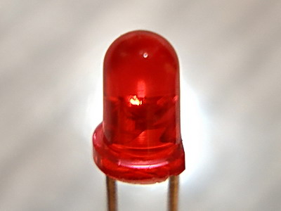
At first, you need 1 led.

Find LPT port on your motherboard. Look for pin's labels.
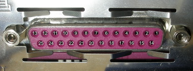
Check numbers.
Join LED to pin 2 and 18.

Now You can use WndLpt to control this LED.

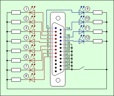
^ Circuit diagram for 12 LEDs
You can directly connect up to 12 LEDs to the LPT port. It's very simple.
Some people prefer to connect only 8 LEDs. It's not a problem. The WndLpt program can manage any quantity of LEDs from 1 to 12.
It's time to make the following circuit. You can see a face of motherboard's LPT port or DB25F Face (or DB25M Back side) on it.
click to enlarge
")
The same circuit is made otherwise.
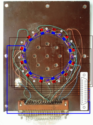
^ LEDs panel example
It is a good day to mount the LEDs to the panel.
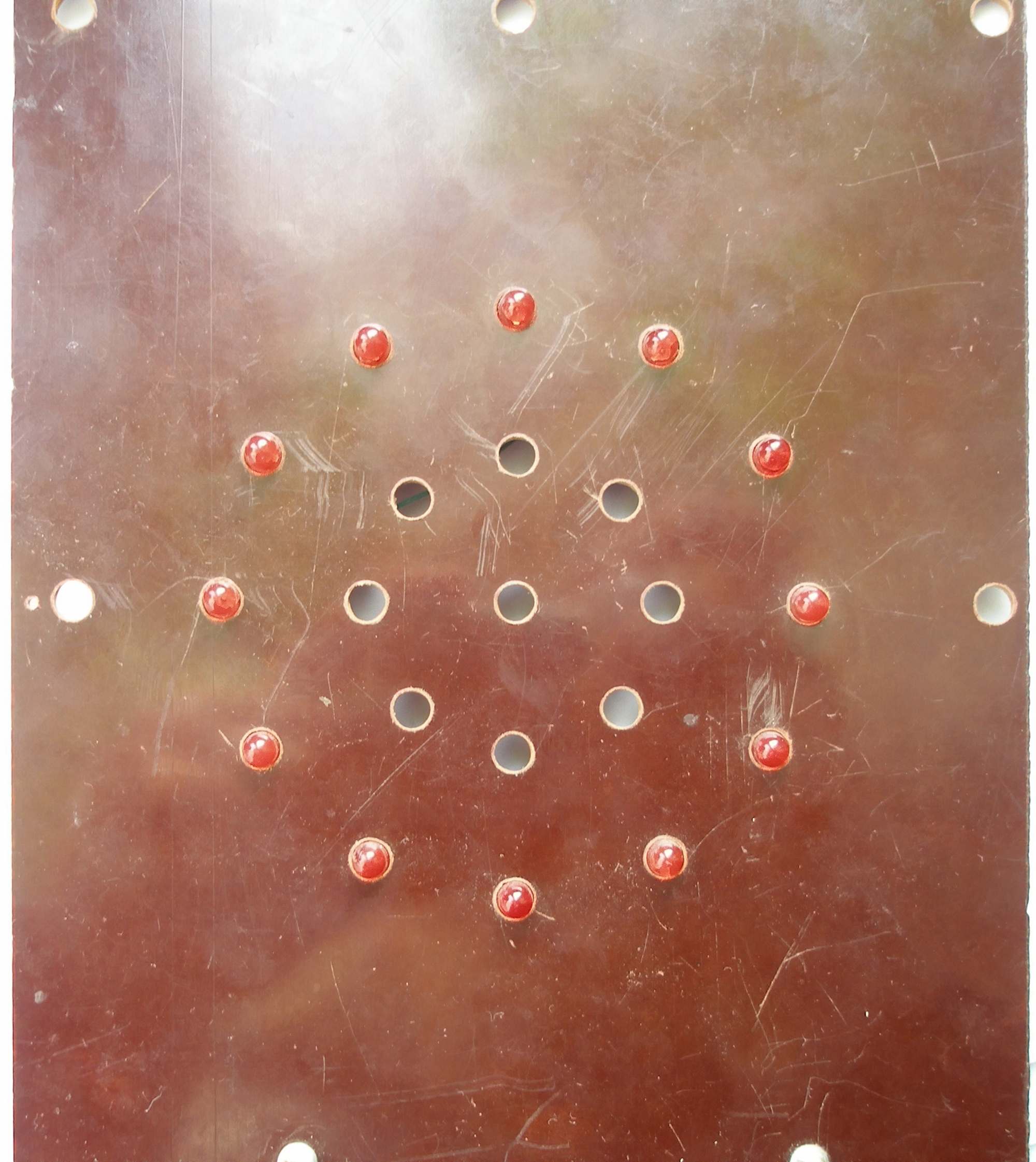
You can take any dark plastic plate and drill 12 holes along a circle.
You have got the following view.
^ Photo session
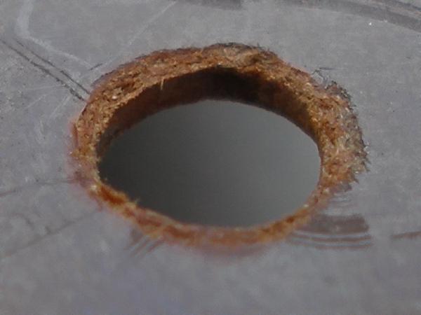
Hole
 |
Led
 |
Panel with 12 LEDs, front side.

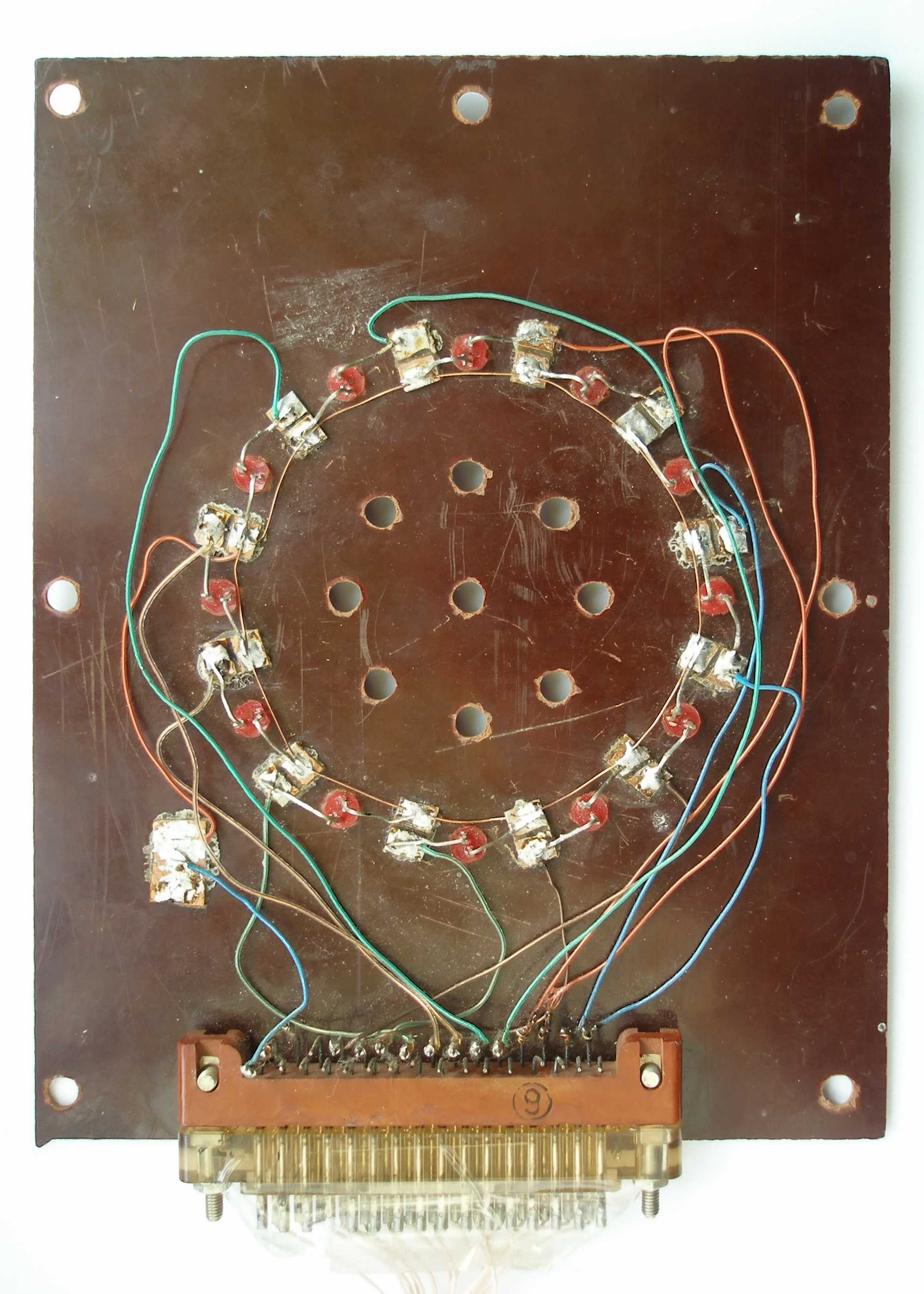
Back side of this panel.
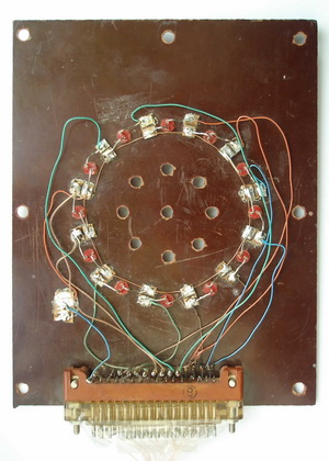
Map-circuit to the panel.
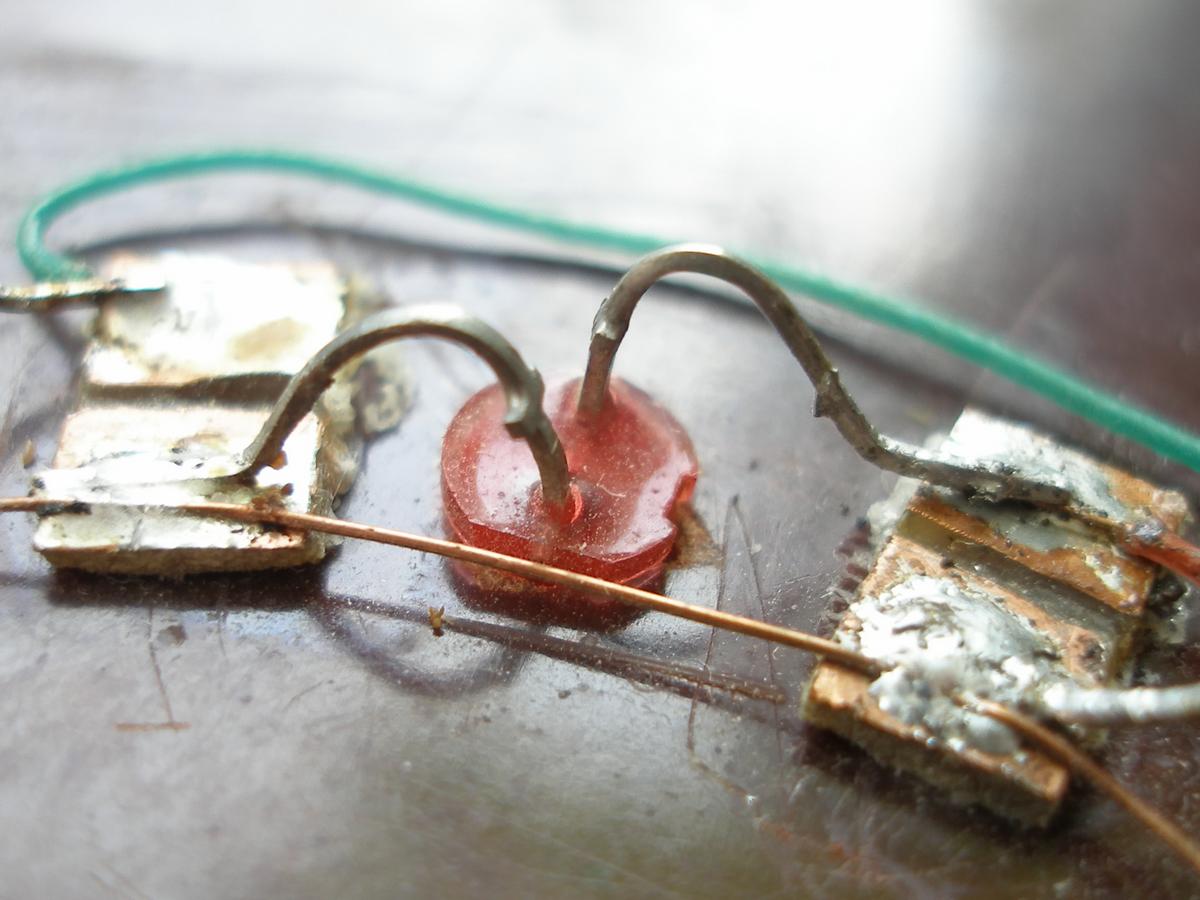
How You can fix the led.

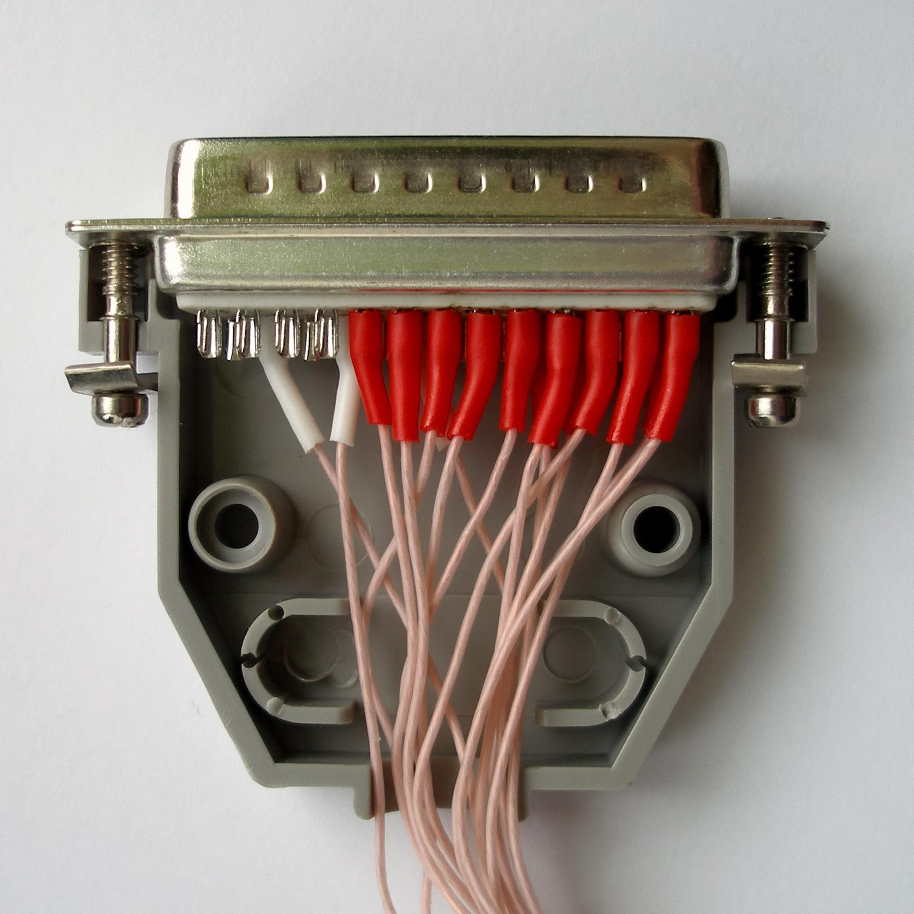
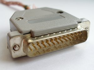
DB-25M Connector

DP-25C case for DB-25M

Connection of DP-25C with DB-25M
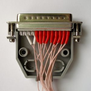
Male connector for LPT port (DP-25C and DB-25M)
Night


^ BIOS settings — only if LEDs glow with low brightness level
Enter to the BIOS. Set this parameters:
[Integrated Peripherals]
Onboard Parallel Port = Enabled or 0x378h
Parallel Port Mode = EPP
Select Save & Exit Setup and press Y.
|


")